Coordinate System
This module defines coordinate systems for horizontal axis wind turbines and provides convenience methods for transforming vectors between the various coordinate systems. The supplied transformation methods are for rotation only and do not account for any offsets that may be necessary depending on the vector quantity (e.g., transfer of forces between coordinate system does not depend on the location where the force is defined, but position, velocity, moments, etc. do). In other words the vectors are treated as directions only and are independent of the defined position. How the vector should transform based on position is not generalizable and depends on the quantity of interest. All coordinate systems obey the right-hand rule, \(x \times y = z\), and all angles must be input in degrees. The turbine can be either an upwind or downwind configuration, but in either case it is assumed that that the blades rotate in the clockwise direction when looking downwind (more specifically the rotor is assumed to rotate about the \(+x_h\) axis in Figure 3). The vectors allow for elementary operations (+, -, *, /, +=, -=, *=, /=) between other vectors of the same type, or with scalars (e.g., force_total = force1 + force2).
Inertial and Wind-aligned
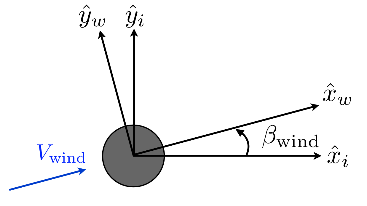
Figure 1: Inertial and Wind-aligned axes.
Figure 1 defines the transformation between the inertial and wind-aligned coordinate systems. The two coordinate systems share a common origin, and a common z-direction. The wind angle \(\beta\) is positive for rotation about the +z axis. The direction of wave loads are defined similarly to the wind loads, but there is no wave-aligned coordinate system.
Inertial coordinate system
origin: center of the tower base (ground-level or sea-bed level)
x-axis: any direction as long as used consistently, but convenient to be in primary wind direction
y-axis: follows from the right-hand rule
z-axis: up the tower (opposite to gravity vector)
Wind-aligned coordinate system
origin: center of the tower base (ground-level or sea-bed level)
x-axis: in direction of the wind
y-axis: follows from the right-hand rule
z-axis: up the tower (opposite to gravity vector), coincident with inertial z-axis
Associated Methods
DirectionVector.inertialToWind |
|
DirectionVector.windToInertial |
Wind-aligned and Yaw-aligned
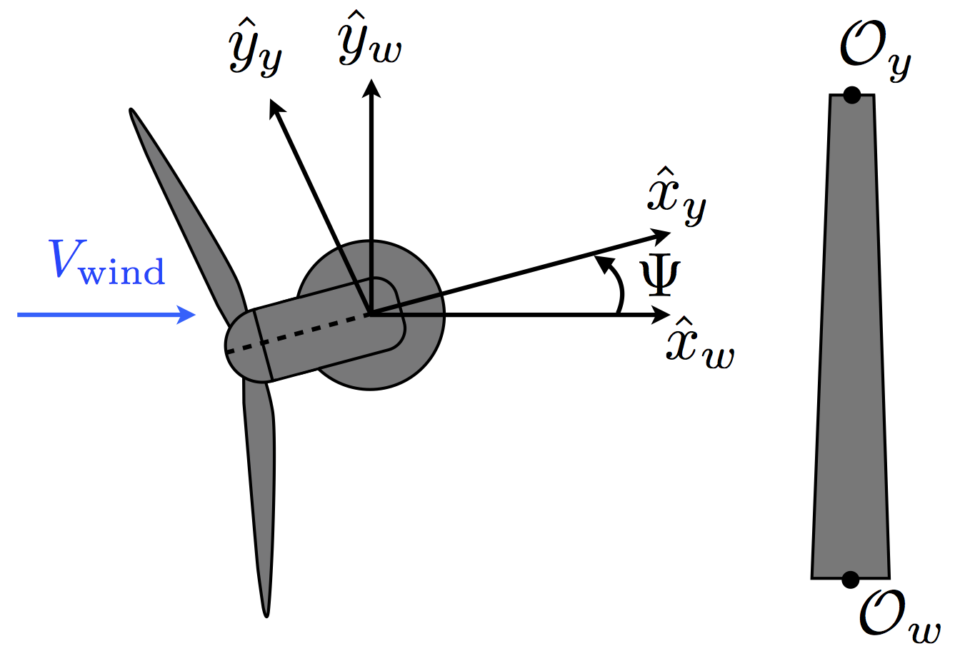
Figure 2: Wind-aligned and yaw-aligned axes. \(\Psi\) is the rotor yaw angle.
Figure 2 defines the transformation between the wind-aligned and yaw-aligned coordinate systems. The two coordinate systems are offset by the height \(h_t\) along the common z-axis. The yaw angle \(\Psi\) is positive when rotating about the +z axis, and should be between -180 and +180 degrees.
Yaw-aligned coordinate system
origin: Tower top (center of the yaw bearing system)
x-axis: along projection of rotor shaft in horizontal plane (aligned with rotor shaft for zero tilt angle). The positive direction is defined such that the x-axis points downwind at its design operating orientation (i.e., at zero yaw \(x_y\) is the same direction as \(x_w\)). Thus, for a downwind machine the \(x_y\) axis would still be downind at zero yaw, but in terms of nacelle orientation it would point from the back of the nacelle toward the hub.
y-axis: follows from the right-hand rule
z-axis: points up the tower (opposite to gravity vector), coincident with wind-aligned z-axis
Associated Methods
DirectionVector.windToYaw |
|
DirectionVector.yawToWind |
Yaw-aligned and Hub-aligned
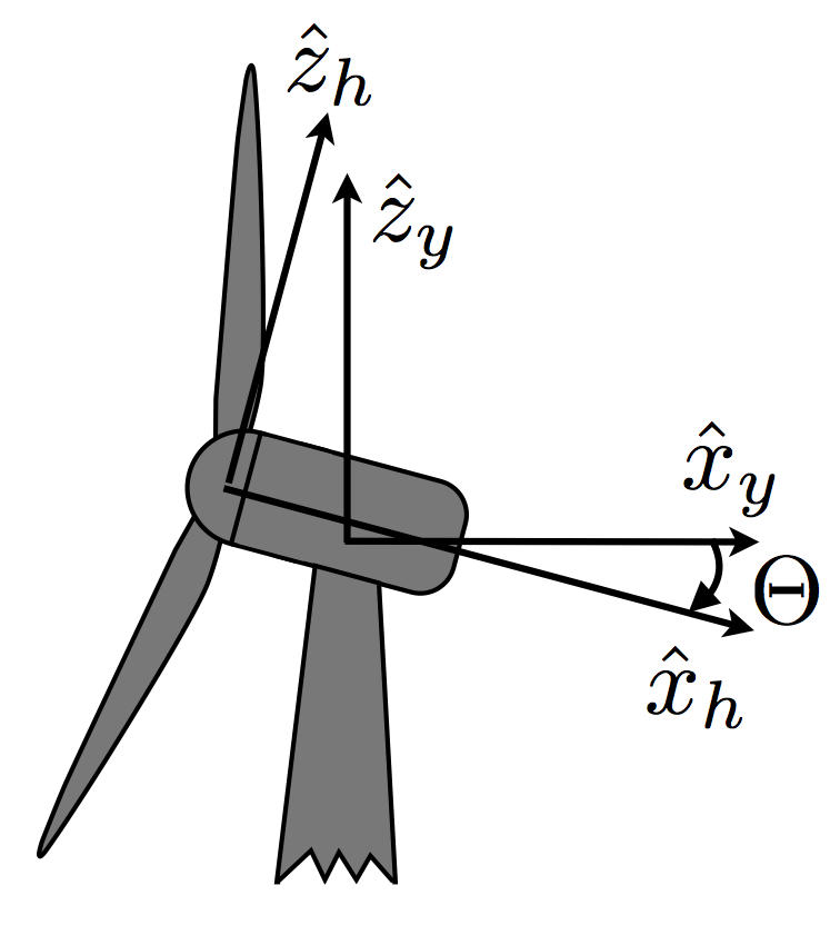
Figure 3: Yaw-aligned and hub-aligned axes. \(\Theta\) is the rotor tilt angle.
Figure 3 defines the transformation between the yaw-aligned and hub-aligned coordinate systems. The two coordinate systems share a common y axis. The tilt angle \(\Theta\) is positive when rotating about the +y axis, which tilts the rotor up for an upwind machine (tilts the rotor down for a downwind machine).
Hub-aligned coordinate system
origin: center of the rotor.
x-axis: along the rotor shaft toward the nominal downwind direction (aligned with \(x_y\) for zero tilt)
y-axis: coincident with yaw-aligned y-axis
z-axis: right-hand rule (vertical if zero tilt)
Associated Methods
DirectionVector.yawToHub |
|
DirectionVector.hubToYaw |
Hub-aligned and Azimuth-aligned
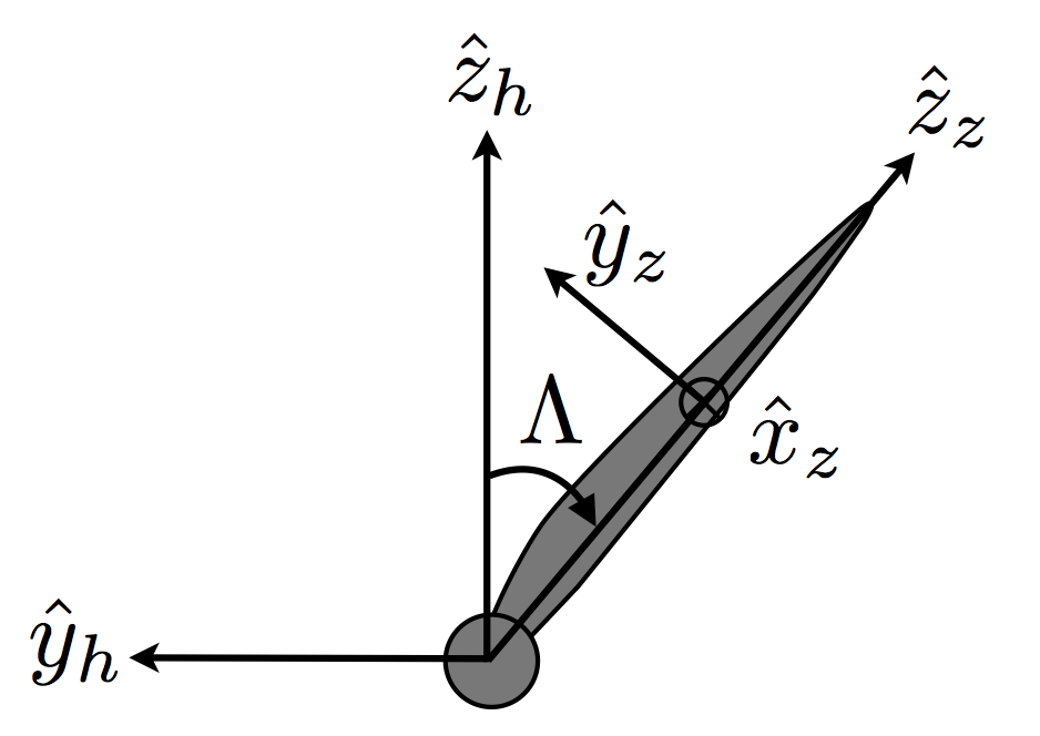
Figure 4: Hub-aligned and azimuth-aligned axes. \(\Lambda\) is the (local) blade azimuth angle.
Figure 4 defines the transformation between the hub-aligned and azimuth-aligned coordinate systems. The two coordinate systems share a common x-axis. The azimuth angle \(\Lambda\) is positive when rotating about the +x axis. The blade can employ a variable azimuth angle along the blade axis, to allow for swept blades.
Azimuth-aligned coordinate system
A rotating coordinate system—about the \(x_h\) axis. The coordinate-system is locally-defined for the case of a variable-swept blade.
origin: blade pitch axis, local to the blade section
x-axis: aligned with the hub-aligned x-axis
y-axis: right-hand rule
z-axis: along projection of blade from root to tip in the \(y_h\) - \(z_h\) plane (aligned with blade only for zero precone)
Associated Methods
DirectionVector.hubToAzimuth |
|
DirectionVector.azimuthToHub |
Azimuth-aligned and Blade-aligned
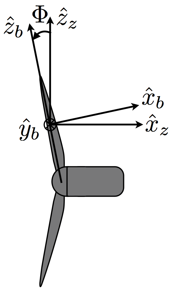
Figure 5: Azimuth-aligned and blade-aligned axes. \(\Phi\) is the (local) blade precone angle.
Figure 5 defines the transformation between the azimuth-aligned and blade-aligned coordinate systems. The \(y_b\) and \(y_z\) axes are in the same direction. The two coordinate systems rotate together such that the \(x_b\) - \(z_b\) plane is always coplanar with the \(x_z\) - \(z_z\) plane. The precone angle \(\Phi\) is positive when rotating about the -\(y_z\) axis, and causes the blades to tilt away from the nacelle/tower for a downwind machine (tilts toward tower for upwind machine). The blade can employ a variable precone angle along the blade axis. The blade-aligned coordinate system is considered local to a section of the blade.
Blade-aligned coordinate system
A rotating coordinate system that rotates with the azimuth-aligned coordinate system. The coordinate-system is locally-defined along the blade radius. The direction of blade rotation is in the negative y-axis. A force in the x-axis would be a flapwise shear, and a force in the y-axis would be a lead-lag shear.
origin: blade pitch axis, local to the blade section
x-axis: follows from the right-hand rule (in nominal downwind direction)
y-axis: opposite to rotation direction, positive from section leading edge to trailing edge (for no twist)
z-axis: along the blade pitch axis in increasing radius
Associated Methods
DirectionVector.azimuthToBlade |
|
DirectionVector.bladeToAzimuth |
Blade-aligned and Airfoil-aligned
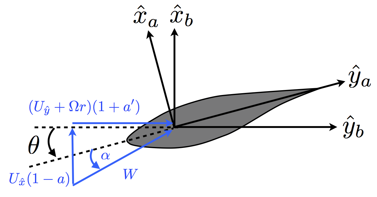
Figure 6: Blade-aligned and airfoil-aligned coordinate systems. \(\theta\) is the airfoil twist + pitch angle. For convenience the local wind vector and angle of attack is shown.
Figure 6 defines the transformation between the blade-aligned and airfoil-aligned coordinate systems. The \(z_b\) and \(z_a\) axes are in the same direction. The twist angle \(\theta\) is positive when rotating about the -\(z_a\) axis, and causes the angle of attack to decrease.
Airfoil-aligned coordinate system
A force in the x-axis would be a flatwise shear, and a force in the y-axis would be an edgewise shear.
origin: blade pitch axis, local to the blade section
x-axis: follows from the right-hand rule
y-axis: along chord line in direction of trailing edge
z-axis: along the blade pitch axis in increasing radius, same as \(z_b\) (into the page in above figure)
Associated Methods
DirectionVector.bladeToAirfoil |
|
DirectionVector.airfoilToBlade |
Airfoil-aligned and Profile
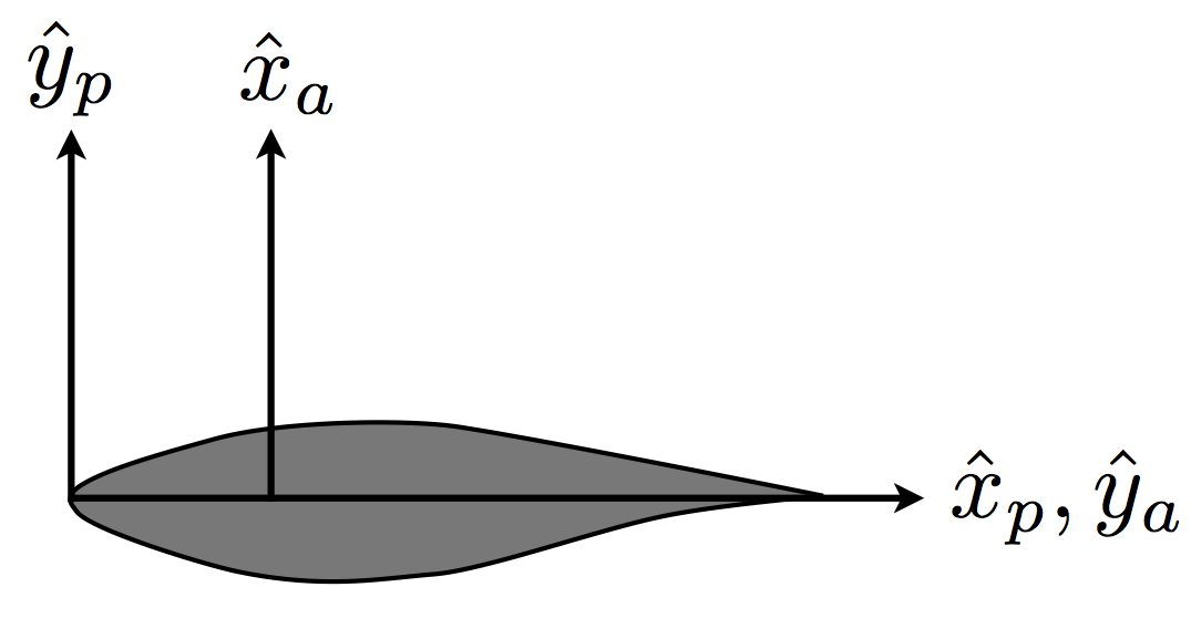
Figure 7: Airfoil-aligned and profile coordinate systems.
Figure 7 defines the transformation between the airfoil-aligned and profile coordinate systems. The profile coordinate system is generally used only to define airfoil profile data.
Profile coordinate system
origin: airfoil noise
x-axis: positive from nose to trailing edge along chord line
y-axis: orthogonal to x-axis, positive from lower to upper surface
z-axis: n/a (profile is a 2-dimensional coordinate system)
Associated Methods
DirectionVector.airfoilToProfile |
|
DirectionVector.profileToAirfoil |