Array Cabling System Design Methodology
For details of the code implementation, please see Array System Design API.
Overview
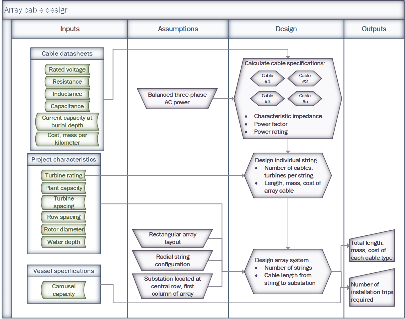
Below is an overview of the process used to design an array cable system in ORBIT. For more details on the helper classes used to support this design please see Cabling Helper Classes.
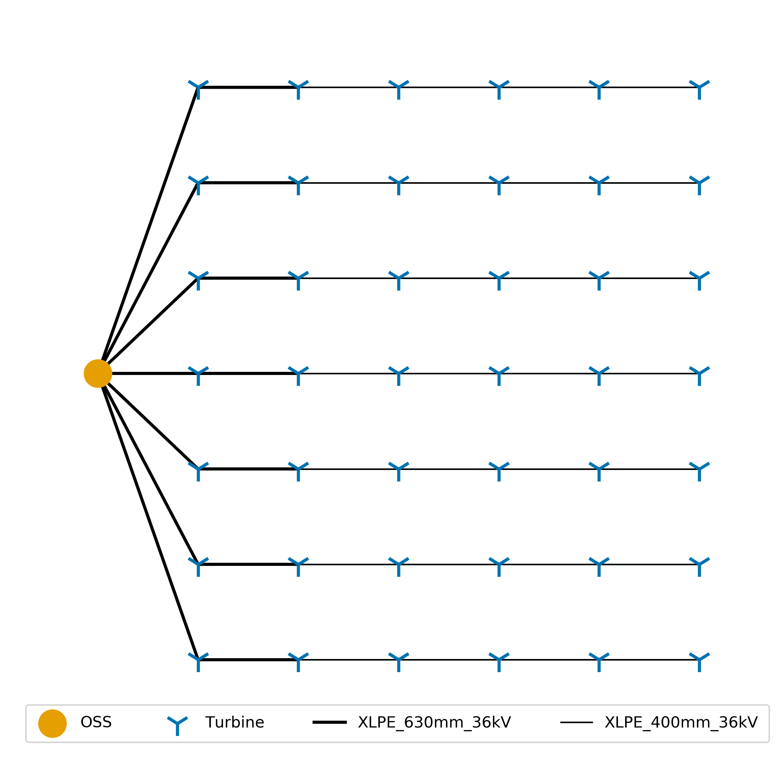
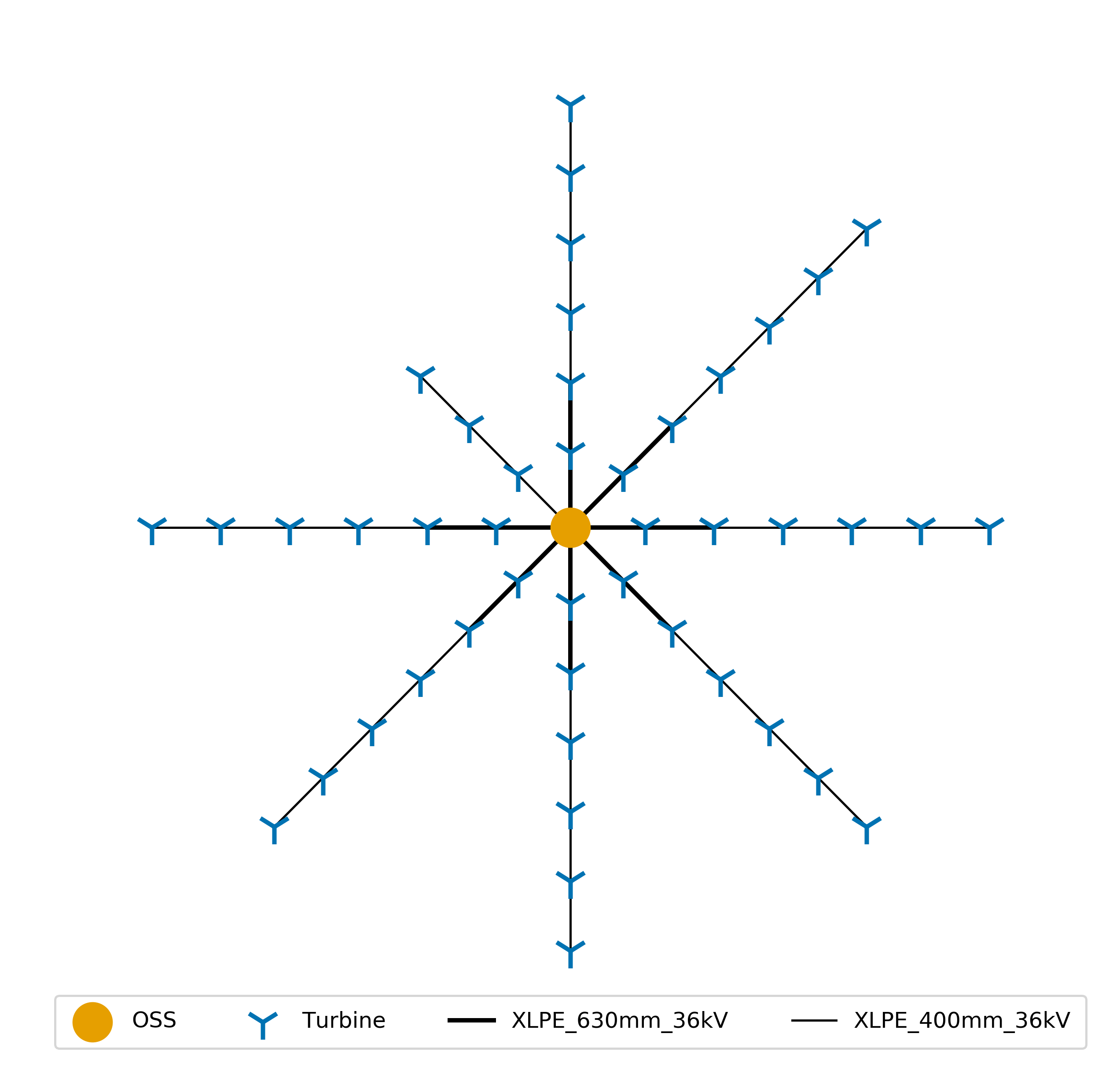
As of the current version of the code there are three array cabling layouts that can be configured in ORBIT: grid, ring and custom. Figure 1 is an example of a grid layout featuring 7 “full-strings” and configured distances between turbines on a string and each row. Figure 2 is an example of a ring layout where the there is a predetermined distance between the first turbines on a string and the substation. This figure is also an example of a “partial string” that is needed to complete the layout. The next sections will go into more detail of the key steps in building out the array cabling system.

|

|
Fig 1. Grid layout with no partial strings |
Fig 2. Ring layout with 1 partial string |
Number of Strings
In order to create the minimum number of strings required to complete a “standardized” array cable layout we must first determine how many turbines can fit on a given set of cable types without overloading them.
Maximum Turbines per Cable
The maximum number of turbines that can fit on each cable is determined by dividing each cable type’s power rating by the rated capacity of the turbine and rounding down to the nearest integer.
Cable.max_turbines = \(\lfloor\frac{P}{turbine\_rating}\rfloor\),
where
Cable.powerturbine_rating = rated capacity of turbineCalculating a Complete String
The number of turbines that can fit on a string is determined by the user configured cable types of the system. Starting from the smallest capacity cable available, turbines are added to the string until that cable’s maximum power capacity is reached. This process is repeated for each of the next largest capacity cables until all cable types have reached their maximum capacity. The number of cable sections added to the string in this process represents the maximum number of cables that can be added to each string.
# Assume that we are using the Fig 1. example so there can only be 6
# turbines contained in a single string of cables
max_turbines_per_string = 6

# Keeping with the Fig 1. example, assume cable1 is a Cable object that
# represents the "XLPE_400mm_36kV" cable from and cable2 represents the
# "XLPE_630mm_36kV" cable. Note that this is sorted from smallest to largest.
cable_list = [cable1, cable2]

# Start with an empty string
cable_layout = []
n = len(cable_layout)

# Loop through the cables as long as we haven't reached the string maximum
# and there are cables in cable_list
while n < max_turbines_per_string and cables:
    cable = cable_list.pop(0)  # remove the first cable in the list

    # Ensure that the most turbines in a string is is lower than the
    # string maximum and the maximum the individual cable can support,
    # then add another cable.
    while max_turbines_per_string > n < cable.max_turbines:
        cable_layout.append(cable.name)
        n = len(cable_layout)
After the above calculation is performed, cable_layout() will contain
a list of cable sections starting from the offshore substation and ending at
the last turbine on a string and will look like the following:
full_string = ["XLPE_630mm_36kV", "XLPE_630mm_36kV", "XLPE_400mm_36kV",
"XLPE_400mm_36kV", "XLPE_400mm_36kV", "XLPE_400mm_36kV"]
In Figure 1, there are 7 of full strings. In the Figure 2 there are 7 full strings and 1 partial string:
partial_string = ["XLPE_400mm_36kV", "XLPE_400mm_36kV", "XLPE_400mm_36kV"]
Number of Strings
The number of full strings is calculated using the equation below,
num_full_strings = \(\lfloor \frac{Plant.num\_turbines}{num\_turbines\_full\_string} \rfloor\)
and the number of partial strings (containing any remaining turbines) is calculated with the following equation.
num_partial_strings = \(Plant.num\_turbines \ \% \ num\_turbines\_full\_string\)
Layouts
Ring
For a ring layout, the substation_distance is used as the radius of
the first row of turbines, spaced evenly around the ring. Subsequent turbines
on a string are spaced using the turbine_distance attribute. An
example of this layout can be seen above in Figure 2.
Grid
For the grid layout, an evenly spaced grid of (x, y) coordinates for each
turbine is calculated based off the turbine_distance,
row_distance, and substation_distance with the offshore
substation being located at (0, (num_strings - 1) * row_distance / num_strings)
Custom
Coming soon!
Section Lengths
The distance between a turbine and it’s subsequent connection determines the
cable length that is required for the array system. These lengths are summed up
and stored in the design_result, which can be utilized by the
array cable installation module.
Process Diagrams
